Modelling Variant Assemblies in FreeCAD
Introduction
FreeCAD offers a wide range of options for modelling of parts. As the software is free and open-source, users are free to imagine their preferred methods to implement features. As a result, a trade-off is created:
- A wealth of tools are made available, presenting the option to create highly complex systems, with deep access to the inner workings of the software.
- The number of options can lead to difficulty for users in choosing a path to meet their goals.
Over recent years, there have been a number of updates that act in service of creating more ‘parametric’ models, though no one method appears to have become particularly dominant, or documented in a systematic manner.
I’ve been developing a design paradigm over the past few months, Variant Assemblies, that I would like to introduce other users to, in service of creating complex, flexible and well-organised models.
The article will presume that the reader has modelled basic parts using FreeCAD’s PartDesign Workbench. It’s also presumed that the reader is willing to take in quite a lot of information about FreeCAD, as understanding its operating behaviour is key to organising robust models.
Parametric Design
In any CAD modelling software, being able to drive models through Parametric Design is a powerful technique to create highly variable parts.
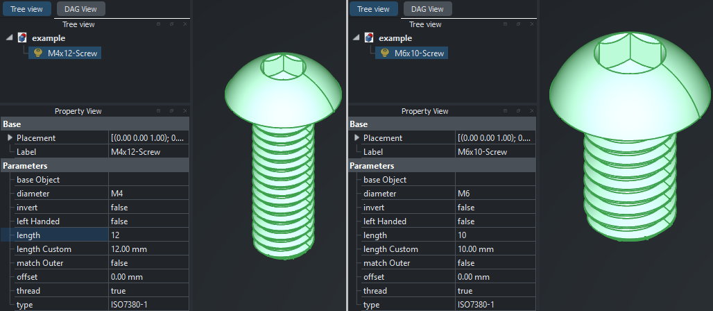
Parametric models are often used to consolidate similar features of a part into an organised, data-driven representation. For example, when modelling a variety of button head screws, a parameter set can be used to represent all subsets of a button head screw within a single ‘model’.
This example is well demonstrated through the Fasteners Workbench. As an example, by modulating the length and diameter parameters of the ‘Hexagon Socket Button Head Screw’ part, an M4x12mm and M6x10mm part can be represented:
This design method can improve organisation for a part model, while reducing repetitive work when the need arises to create a similar model.
An Assembly is a group of parts that form a complete system or product. Two examples of assemblies are:
- A table, consisting of four ’leg’ parts and a ’table top’ part.
- An axe, consisting of a ‘haft’ and ‘head’ part.
Simlarly, a Sub-assembly is a group of parts that form a sub-system. Two examples of sub-assemblies are:
- A drawer, consisting of four ‘panels’ and two ‘slides’.
- A fastener, consisting of a ‘screw’, ‘washer’ and ’nut’.
Sub-assemblies differ from assemblies by being designed to be incorporated into a larger assembly system. They are typically organised to reduce repetition. For example, the ‘drawer’ described above will not need to be repeated in design four times when assembled into a four-drawer system, and the sub-assembly can be used to encapsulate the parameters of a single drawer.
By applying parametric design principles to parts, sub-assemblies, and assemblies, a single model can become highly modular, yet automatic in adapting to configuration.
Setting up the environment
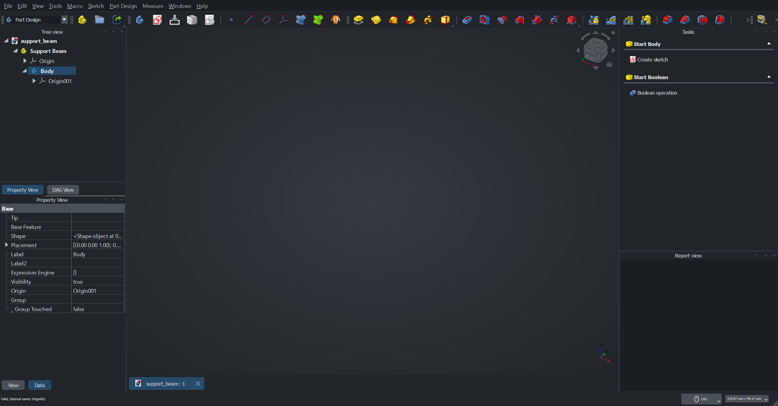
The environment used for this article shows the views necessary to create models with the Variant Assembly workflow.
- The Tree view shows an overview of the parts and operations of the models.
- The Property view will be used to organise parameters for the models.
- The DAG view will be used to verify the models integrity.
- The Task view provides the ability to apply operations to parts.
- The Report view will be particularly useful to determine whether any mistakes have been made.
It’s recommended that the user elects for a separate tree and property view when using this method.
Variant Assembly pre-requisite knowledge
To introduce concepts that are utilised in this article, a simple Cuboid object will be modeled, with a variable ‘Length’, ‘Width’ and ‘Height’.
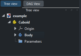
The cuboid model will consist of a Part with a Part Design Body child
along with a Group child used to organise parameters.
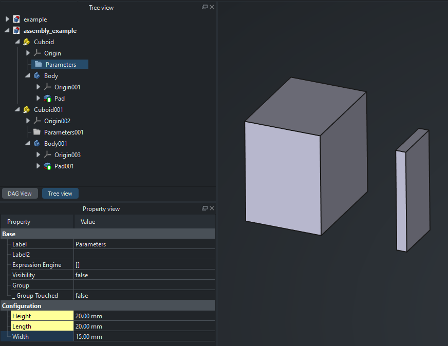
Two cuboids will be created within the same document, with differing dimensions, while being defined by the same model.
Directed acyclic graph
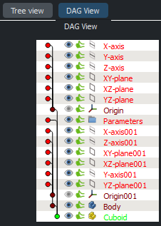
FreeCAD’s modelling system is designed using a directed acyclic graph. When a models geometry, positioning and other properties are calculated, the ordering of calculation occurs in a top-to-bottom fashion. This means that care must be taken to avoid creating a cyclic dependency, an example:
- Cuboid
Parthas aWidthproperty, and aBodychild. - The
Bodychild defines aSketch, which references theWidthproperty ofPart. - The ordering of calculation is now indeterminate, as the graph is no longer able to traverse in a single direction.
This is the primary reason for attaching properties to a Parameters Group
as opposed to the Cuboid Part, and reduces risk of cyclic dependency.
Properties
Properties are a relatively underutilised feature within FreeCAD, generally
used by more advanced users. In this example, properties will be added to the
Parameters Group object.
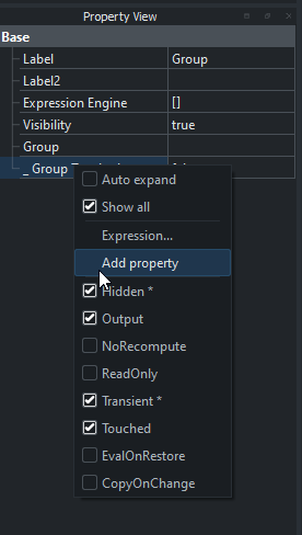
Users are able to add properties to their models by selecting the Show all toggle within the Property View. This will enable the Add Property option along with a number of property parameters.
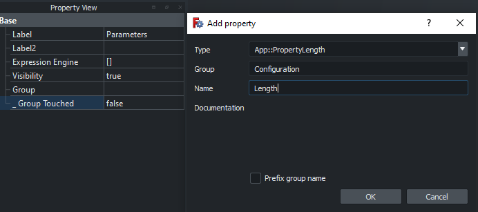
By selecting ‘Add Property’ a configuration window will pop up, allowing the
user to select the property type, group, name and documentation. For now
the ‘Length’, ‘Width’ and ‘Height’ properties of type App::PropertyLength
will be added to the standard ‘Configuration’ group.
The properties should now be visible in the property view, and can be modified by the user to values of their choice.
Expressions
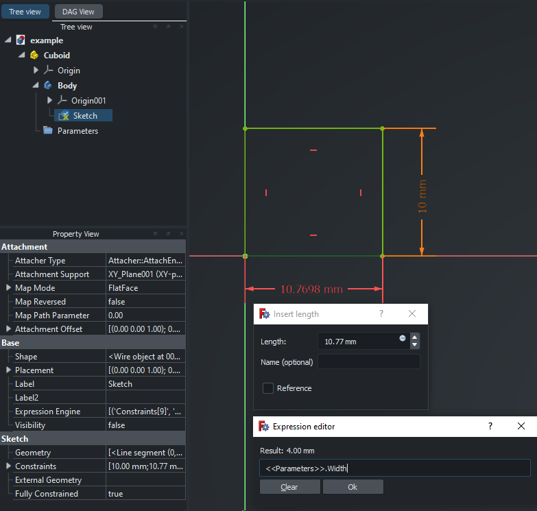
By creating a Sketch with a rectangle geometry, constraints can be
applied to demonstrate expressions. The ‘fx’ icon can be clicked to bring up
the Expression editor.
Expressions can be used to reference properties, constant values and
functions to parametrically drive a property. In this example, the
<<Parameters>>.Width and <<Parameters.Height>>properties are used to
set the geometry properties of the Sketch rectangle.
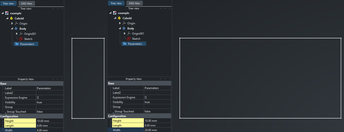
The Parameters Group properties can now be edited, and Sketch
constraint values will be calculated and update accordingly.
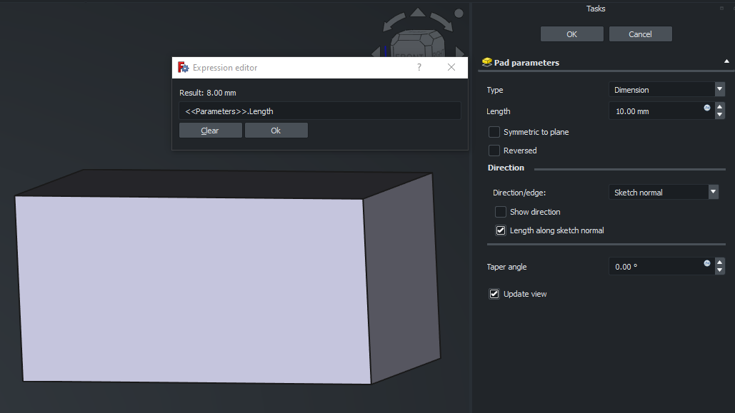
Expressions are usable in a variety of places in FreeCAD. Including in tasks, and can be used in this example to drive the ‘Length’ paramter of the Pad.
See Expressions for more comprehensive usage information on both expressions and properties.
Variant Links
Links in FreeCAD allow the user to create object references in both the
same and other documents. In this example, a second document is created with a
Link object.
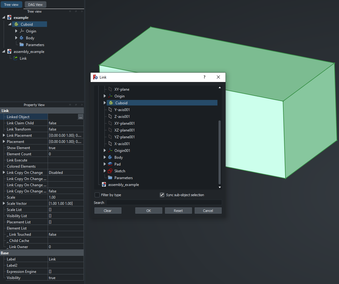
The Linked Object property of the Link can then be set to the Cuboid
Part previously made.
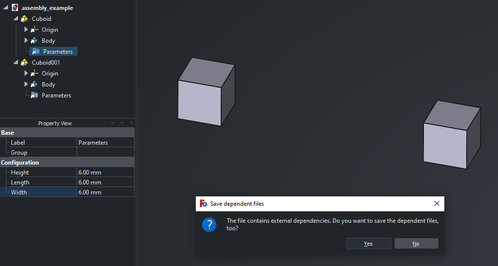
This step can be repeated, and a transform applied to the second cuboid to
move its position. Within the tree view, the Cuboid Link has access
to the original Cuboid Part, along with its children. The Parameters
Group within this link can be edited. However, on doing so, both of the
linked cuboids will update, and the source Cuboid Part will reflect the
same changes to those parameters.
This is the standard behaviour of a Link in FreeCAD, but can be altered
to allow properties to be modifiable after the link is made.
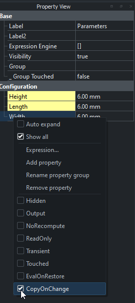
The properties that are modifiable after being linked to are marked with the
Copy On Change property. In the original Cuboid Part, the properties
of the Parameters Group can be right-clicked, and have their
CopyOnChange property selected.
The Part object itself is the linked object in our assembly. FreeCAD
necessitates that the parent is aware of which child objects will contain copy
on change parts. This can be accomplished by creating an
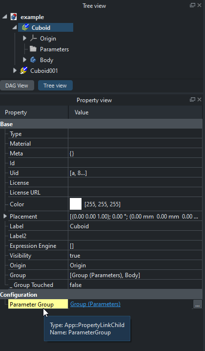
App::PropertyLinkChild property within the Cuboid Part Configuration
group, called ParameterGroup, which can have its linked object set to the
Parameters Group, and be have its CopyonChange property selected.
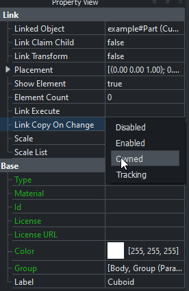
Now, in the assembly file, the Link Copy On Change parameter in both
cuboid Links can be changed to Owned.
The newly owned cuboid Links are now able to have their respective
Configuration properties changed independently, and avoiding change to the
underlying file.
Summary
By understanding:
- The directed acyclic graph calculation engine underlying FreeCAD.
- Object properties.
- Driving properties with expressions.
- Variant links to create parametric objects.
An understanding of the core parts of the Variant Assembly workflow are established.
A Variant Assembly design example
The previous example gives an introduction to all concepts for this workflow. In the following example, we will apply the same core concepts, albeit with a little more systems-oriented thinking to create an example of the powerful nature of this workflow.
This can be exemplified by choosing the project - 40x40 Aluminium Extrusion Shelf with the following parameters:
- Number of shelves.
- Width/depth of all shelves.
- Height for each shelf.
- ‘Light/Heavy’ load options for each shelf.
The project will rely on designing the model within base FreeCAD, without the use of external workbenches. One exception will be made: the Fasteners Workbench. This is because re-modelling already well designed parts doesn’t contribute any worthwhile information to the article.
